Flow Cells for Carbon Electroreduction
9 min. read
Let’s start with some definitions.
Definitions
| Term | Definition |
|---|---|
| Current density | The amount of charge flowing through a particular area per unit time (units of ⁍) |
| Reference electrode | A stable electrode used in electrolysis whose voltage acts to specify the voltage more precisely of the working electrode |
Types of Flow Cells
See Liang et al.[^1] for further details on these two design types, along with others.
Standard electrolysis is often done in an H-Cell, which gets its name from the shape of the two beakers and salt bridge that comprise it.
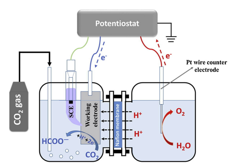
A standard electrolysis H-cell.
In general, an H-cell can be used effectively in a lab-scale setting to test, for instance, different catalysts, electrode morphologies or electrolytes. However, it is not suitable for industry-scale cells. This is due to the time-decreasing current densities (sometimes referred alternatively as mass flow) one observes in such a cell. Because the electrolyte and products are not circulated away from the electrode, there will be a build up of compounds on or near the working/counter electrode surface which overall decreases cell performance. This can be best seen when a gas evolves such as in the oxidation of water.
Microfluidic Flow Cell
Microfluidic flow cells (MFCs) are a promising alternative to traditional H-cells. In contrast to the latter, they can sustain highly alkaline environments (e.g. when using something like as an electrolyte) compared to H-cells, in which dissolved in solution will quickly reduce to carbonate that impedes cell performance.
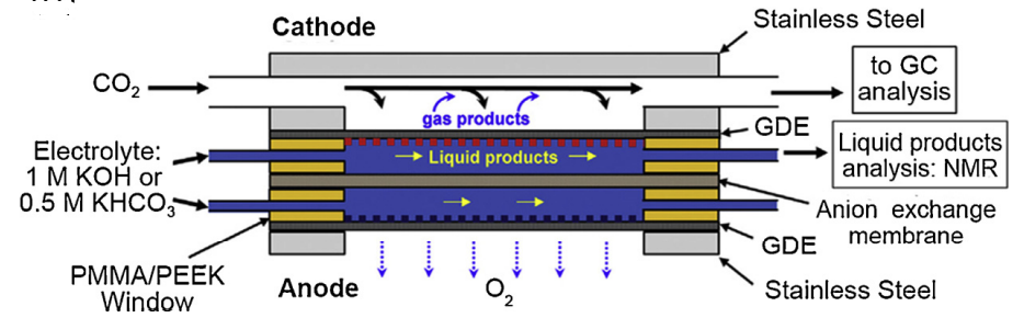
An example of a conventional microfluidic cell
In reference to the above:
- PMMA = polymethyl methacrylate AKA acrylic plastic
- PEEK = polyether ether ketone is another form of thermoplastic polymer
Though we are not currently concerning our research with MFCs, it is worth stating here concisely what some of the advantages and disadvantages of this design are:
| ✅ Advantages | ❌ Disadvantages |
|---|---|
| Can sustain strongly alkaline environments compared to H-cells due to circulation of electrolyte and products | The varying pressure across the cell membrane (the forces through the centre of the membrane are far greater than where the PMMA/PEEK window “supports” are) prohibits (at the moment) scale-up of such reactors |
| Has been used to achieve really high selectivity of ethylene with Cu-based catalysts. Citing FE at a current density of with a 10 M electrolyte | Design modifications required in order to accommodate CO2RR to something like which requires generally a second gaseous inlet/outlet stream running over the anodic compartment |
PEM Flow Cell
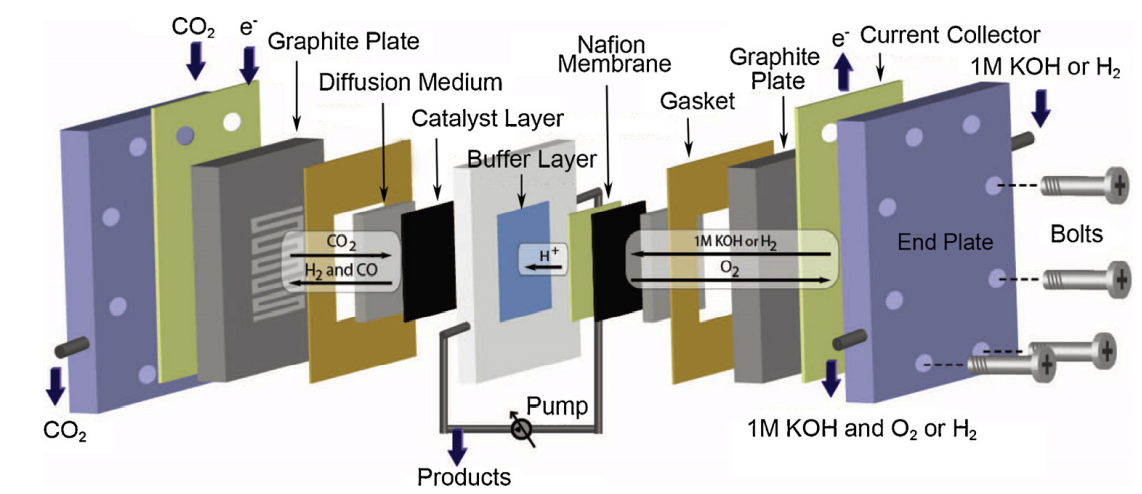
This is a type of flow cell used in CO2RR that has been adapted from fuel cells or water electrolyzers. It is an interesting design choice because the constant circulations of reactants allow a host of exciting benefits, including:
- Increased concentration at the working electrode
- Potential for higher mass transfer/current density through the cell
- And hence the viability of up-scaling to a large-scale commerical application
One of the additional parameters categorically different from a PEM flow cell to an H-cell is the ability to deliver the reactants of both the anodic and cathodic compartments in three different manners: (i) both in liquid phase, (ii) gaseous and a liquid-phase anolyte, or (iii) both reactants fed in in a humidified (read gaseous) way. In general, delivery with at least the in gas phase will give the best performance, as it is able to overcome the low solubility of in aqueous electrolytes.
Compared to an H-cell, a PEM flow cell does not generally use a reference electrode.
Components of a PEM Flow Cell
Gas Diffusion Electrode: The purpose of this electrode is to serve as the site of reduction or oxidation. In general, teflon (PTFE) or carbon cloth/paper electrodes are common for their ability to increase working surface area for the redox reaction.
It is important that the electrode be semi-porous so that the gas can penetrate the interior of the electrode and reach the bulk electrolyte in the cell. A vanilla GDE is generally pre-treated with an electrocatalyst and/or metal-coating, depending on the particular product to be obtained. Good GDEs will also be strongy hydrophobic, since accumulating water on the surface of the electrode will usually lead to it preferentially reacting to form .
Current Collector: The current collector (and flow plate) serve to distribute the voltage potential provided by the potentiostat to the working and counter electrodes and to direct the flow of reactants across the electrolyte as desired. Many of the materials used for the electrodes, like the GDEs highlighted above, are either not strongly conductive (carbon paper) or very strong insulators (teflon). The only way for current to be dispersed across the electrode, then, is via the use of a current collector in conjunction with a conductive metal coating on the electrode.
At a basic level, a current collector could be a simple pin contacting the electrode and protruding from the cell for electrical connection to the voltage source. The issue here is that there is an extremely uneven current distribution, causing a very high, localised current density. This is not good for long-term (or even short-term) performance. Far better is to have a conductive plate that contacts the entire electrode, allowing for a much more homogeneous distribution of charge.
Polymer electrolyte membrane (PEM): There are families of different PEMs that one can consider when fabricating such a flow cell: cation-exchange membranes (allowing positive ions in electrolyte to permeate), anion-exchange membranes (allowing negative ions in electrolyte to permeate) and bipolar membranes. Each serves the purpose of acting as the salt bridge equivalent, as discussed in the Electrolysis background.
The type of membrane that is used is tied strongly to the cell conditions one expects or desires. CEM is generally associated with acidic electrolytes, whilst AEM with alkali environments. Another factor to consider is that CEMs promote proton transfer (), meaning in papers where researchers have wanted to observe syngas formation (), it was preferential to use a CEM even with an alkali electrolyte like . When formation of is to be limited, then, AEMs are a good choice.
References
[^1] Liang, S., Altaf, N., Huang, L., Gao, Y., & Wang, Q. (2020). Electrolytic cell design for electrochemical CO2 reduction. Journal of CO2 Utilization, 35, 90–105. https://doi.org/10.1016/j.jcou.2019.09.007